Published 2024-06-28.
Last modified 2024-07-31.
Time to read: 13 minutes.
This article discusses issues encountered when upgrading modular PSUs conforming to the family of standards for power supplies designed for ATX form factor motherboards. The major topics discussed are:
- ATX specification
- Important connectors, such as SATA power and Mate-n-Lok
- Modular PSUs and cables
- PSU tester
- Corsair PSUs
- PSU Manufacturers
- EVGA SuperNOVA 1000 GT PSU
Most of the information in this article generally applies to all modular PSUs.
ATX12V Specification
The ATX PSU specification had two major revisions, the ATX 2.x and ATX 3.x PSU specifications. Collectively, they are called the ATX12V specifications. ATX12V PSUs are the most common types of PSU today, having evolved from the original ATX PSU specification.
The ATX12V standard is upwards compatible. This means you can install a PSU that conforms to a more recent version of the standard in an older motherboard that only supports an older version of the standard. For more information, please see the ATX / ATX12V Power Supply Design Guide.
ATX 2.x PSUs
The current version of the ATX12V standard, v2.53, was released in December 2021. The most recent version of the standard that I could find a PDF of is ATX Specificaiton Version 2.2, published in 2004.
This is the ATX 2.2 24-pin motherboard power connector pinout:

Pin numbering is clearly shown
The above diagram shows that pins are numbered in columns from left to right. pin 1 is at the top left, and pin 24 (the highest-numbered pin) is at the bottom right.

The ATX12V specification includes a 24-pin main connector and a 4-pin (2x +12v, 2x GND) connector for auxiliary CPU power.
Each of the wires in a CPU cable can carry 4 amps at 12 vdc, or 48 watts. A 4-pin CPU connector can therefore deliver up to 192 watts of power, which is enough for most CPUs. An 8-pin connector can deliver up to 384 watts of power, twice as much as a 4-pin connector.
Most consumer motherboards are either ATX12V or EPS without the optional 4-pin connector. The EPS Specification section below has more information.
For ATX12V-compliant motherboards, one 4-pin connector is attached to the auxiliary power connector.
ATX 3.x PSUs
ATX 3.x is upwards compatible with ATX 2.x, which means that an ATX 2.x tester can determine if an ATX 3.x PSU works, except for being able to test either of the new high-power PCIe 5.0 connectors for top-tier GPUs.
ATX 3.0 introduced the 12VHPWR connector, which was problematic and was replaced by the new 12V-2×6 connector for ATX 3.1. To learn more about ATX 3.0, see What is ATX 3.0 and why you need to know before your next PC upgrade.
Anandtech has an excellent description of ATX 3.1 that explains why the 12VHPWR connector introduced by ATX 3.0 was a failure and discusses the 12V-2×6 connector introduced by ATX 3.1 to replace the ATX 3.0 12VHPWR connector.
I would not install an ATX 3.x PSU unless the computer had an NVIDIA 4090 because this PSU standard is still bleeding edge.
EPS Specification
The Entry-Level Power Supply Specification (EPS) is a derivative of the ATX specification. It was intended for high-end PCs and entry-level servers, and was originally published by the Server System Infrastructure forum. The latest EPS specification is v2.92.
The EPS specification includes the 24-pin main connected adopted from ATX12v, an 8-pin (4x +12v, 4x GND) connector for auxiliary CPU power as well as two optional 4-pin connectors. PSUs with a capacity up to 800 watts have one 4-pin 12V connector, while higher-capacity PSUs have two 4-pin 12V connectors.
The shorthand “(4x +12v, 4x GND)” means that each of these cables contains four 12v wires and four ground wires. Some manufacturers write this as “EPS/ATX12V 8(4+4)-Pin”.
EPS-compatible motherboards require two 4-pin connectors to be ganged together and plugged into the motherboard’s 8-pin socket. By adopting a 4+4 configuration, PSU manufacturers can ship products that are compatible with motherboards that use either the ATX12V specification, or the EPS specification. An 8-pin EPS connector is compatible with half of the ATX12V 4-pin connector. For EPS-compliant motherboards, two 4-pin connectors are ganged together into the 8-pin socket, and any additional 4-pin connectors are also connected.
ATX12V PSUs can be used in EPS systems, but it is not recommended. Half of the 8-pin connector will remain unpopulated, as well any additional 4-pin connectors. However, this is not recommended, as the system may not be able to draw the necessary current.
ATX: Four Special Wires
Four of the wires in 24-pin ATX v2 and v3 cables have special functions. It is important to test new PSUs before you install them, to verify that the signals in these wires are functioning properly. This section describes the signals to be tested. The next section describes how to test them.
- PS_ON (power on) on pin 16 is a signal originating from the motherboard to the power supply. This pin’s voltage is internally pulled up to +5 V inside the power supply. The PSU will attempt turn on after the voltage on this pin is pulled low by being connected to ground.
-
PWR_OK (power good) on pin 8 is an signal from the power supply
that indicates that the +5VDC and +3.3VDC voltages provided by the PSU’s 24-pin connector have stabilized.
The motherboard will not attempt to power up unless this signal is provided.
Normally the singal remains low for a brief time (100 to 500 milliseconds) after the PS_ON signal is pulled low;
however, the signal will only go high after the PSU ascertains that its +5VDC and +3.3VDC outputs are stable
and within normal operating parameters.
PG was inherited from the original IBM PC in the early 1980s. The PC’s PSU had a PG signal because of the RAM chips it used and the specific internal design of the PSU. The PSU’s design was such that the -5V rail wasn’t stable immediately, and this in turn meant that the RAM wasn’t 100% reliable at initial power on, so if the mobo tried to boot, it might crash due to memory corruption. PG was designed to make the mobo wait (in hardware) a few hundreds of milliseconds before booting so that the system would be stable.
0 ms would indicate that the PS is telling the mainboard that power is good from the get-go when in fact it may not be.
Even today there is a small window of opportunity at the instant of switch on (around 50-100 ms) where supply voltages aren’t stable. If the system tries to begin POST during this time it may crash, so PG is used to generate a hardware delay so that booting doesn’t start until the voltages are stable. A 0ms PG means that the PG signal is probably faked.
Modern motherboards have largely done away with the need for hardware PG (they either simply don't require a delay, or implement the delay by other means), although it is still part of the ATX specs, page 21.
A faked PG signal says nothing about the actual functionality of the PSU, and simply cannot be used as a judgment of the functionality of the supply, although the use of a faked PG design can imply that the PSU is of an inferior design quality. - +5 VSB (+5 V standby) on pin 9 supplies power even when the rest of the supply wire lines are off. This can be used to power the circuitry that controls the power-on signal.
- +3.3 V sense on pin 13 allows the PSU to sense the voltage drop in the PSU wiring.
SATA Power Connector
Examples of SATA and SATA3 drives include 2.5” 5200 RPM notebook drives, 2.5” SSD drives, and 3.5” 7200 RPM desktop drives. NVMe drives do not use SATA connectors.
These drives have two connectors: a signal connector (also known as a data connector), and a power connector.
SATA and SATA3 power connectors must provide +12vdc and +5vdc to the drive they are plugged into.
Both connectors are keyed. Keying prevents mating in an incorrect orientation.
 near pin 1")
This article has a good discussion about SATA power connectors.
Mate-n-Lok Connector

People often refer to a Mate-n-Lok connector as a Molex connector; however, even though the term “Molex connector” is often used to refer to all nylon plugs and receptacles, the original Molex connector is incompatible with connectors used in the computer industry.
Modular PSUs
This article specifically discusses replacing / upgrading modular PSUs. Most of the issues raised do not arise unless the PSU is at least partially modular.
Non-modular PSUs lack one significant source of failure: only the cables provided with the PSU can be used because they are permanently attached.
Cables
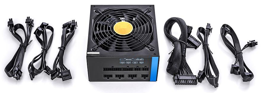
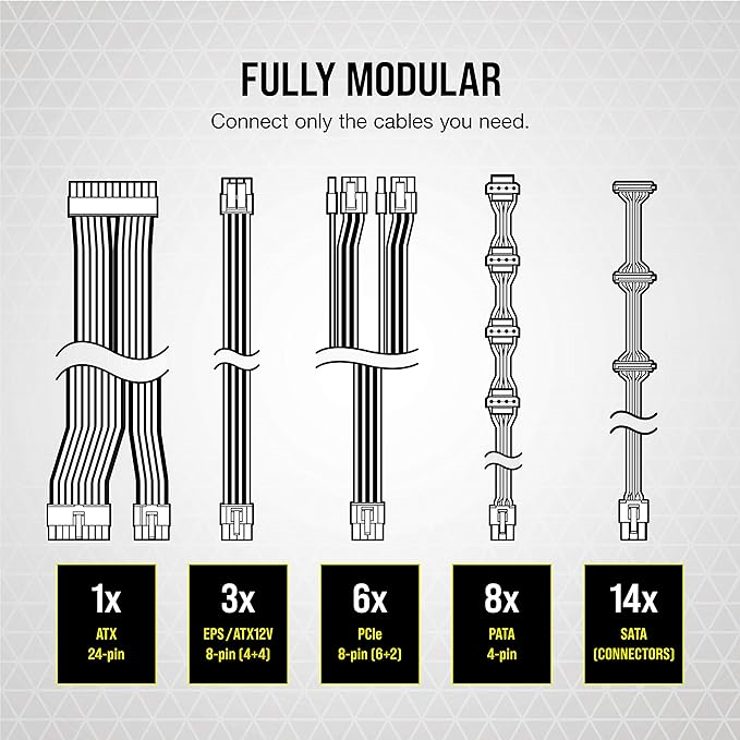
Modular power supplies have removable cables; you only connect the cables that you need. This makes building computers easier and improves airflow within a computer.
If you attach a cable from a modular PSU to a modular PSU of a different model, then some or all the electronics in your computer may be fried. The actual results depend on many variables.
You might want to get in the habit of marking each end of every cable with nail polish, and also paint a dab on a small portion of the PSU label as well. Using a unique color of nail polish for every different model of PSU that you own will make it easy to recognize the cables that came with each model of PSU that you have. Nail polish will not stick to the plastic used in some connectors, so if that is the case, place the dabs of nail polish on the wire sleeves, if present, or on the wires themselves.
Replace The Cabling When Replacing a Power Supply

When replacing a power supply with another model or brand, even if it seems almost identical, also replace the power cabling. Seemingly trivial differences between PSU models can cause the new power supply to fail if an old power supply's cabling is used, and the components it is electrically connected to might be damaged.
💥 💥In other words, unless you are really, totally, absolutely 100% sure that the cables are in every way identical, replace them when you replace the PSU. Leaving the previous cabling in place and just swapping the power supply can fry the power supply, the motherboard, and more.
PSU Tester
Always use a PSU tester to test a new power supply before you install it.
The PSU tester that most people that I know own has poor documentation. This article attempts to address that.

This PSU tester has no battery and is only powered by the PSU’s 20-pin or 24-pin interface. If no power is provided by the 20-pin or 24-pin interface, the tester will not function. You can plug in other cables at the same time; however, if you attach a PCIe 4-pin and a EPS connector, or a floppy connector with either the PCIe 4-pin or the EPS connector, you will not be able to determine which connector is reported by the +12V2 readout. It is better to test the PCIe 4-pin, EPS connector and floppy connectors separately.

To use the PSU tester shown above, plug the 24-pin cable between the PSU and the right-hand-side connector on the tester. Now turn on the PSU. You should observe:
- The tester might start beeping; this may not be signficant.
- As previously mentioned, PG stands for Power Good, also known as “Power OK”. The motherboard will not attempt to power up unless this signal is provided. The LCD indicates how many milliseconds it takes to receive the Power Good signal from the PSU. If it reads 0, your PSU does not conform to the ATX12V specification, although it might work with some motherboards. If you test a new PSU, and get a zero value for PG, and you trust the tester, return the unit.
- The text under the +12V2 heading will flash LL when no device is connected. You can usually ignore this readout. Its value is only relevant when a 4-pin, 6-pin, 8-pin or a floppy disk connector is used by an PCIe device, IDE (HDD), a SATA drive, or a floppy disk.
Corsair PSUs
I have been purchasing PSUs for the computers that I build since the early 1980s. Some of those PSUs were made by Corsair.
Following the lead of other vendors, Corsair introduced its first fully modular PSU in 2012 for computer enthusiasts to build their own computers.
Technical support is not provided, citing ‘legal liability issues’. I call bullshit.

Technical information for specific products is not organized properly and contains inaccurate compatibility statements. Providing incomplete information seems to be a goal, perhaps again due to paranoia about legal liability. I attribute the inaccuracies to sloppiness.
Connector Labels
Corsair has been inconsistent about how it has labeled the modular connectors over the years.
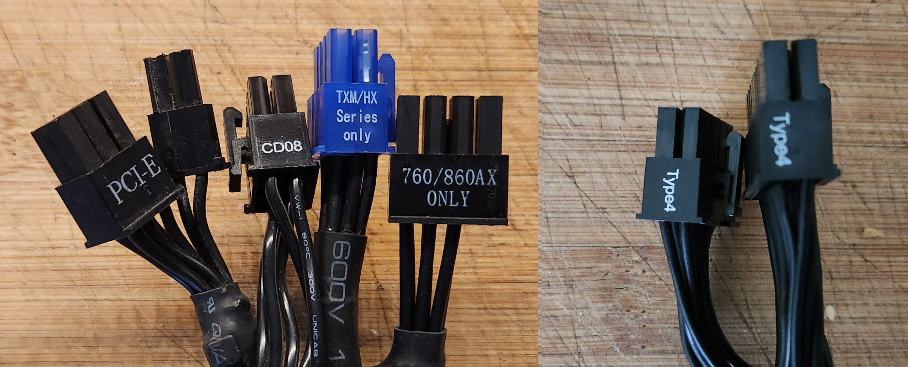
In the above photograph, we see:
- Three connectors were clearly labeled with the PSUs that they were compatible with (“TXM/HX Series only”, “760/860AX ONLY”, “Type4”)
- One connector had a label that only had meaning if you knew the PSU it was for (“CD08”)
- One connector labels its purpose but does not provide any clue about the PSU that it was designed for (“PCI-E”). As we shall see, not all PCI-E cables are created equal.
Not shown are connectors without labels.
The inconsistent and unhelpful labeling continues today.
Inaccurate Compatibility Statements About Cabling Variants
The main Corsair product page for PSUs says:
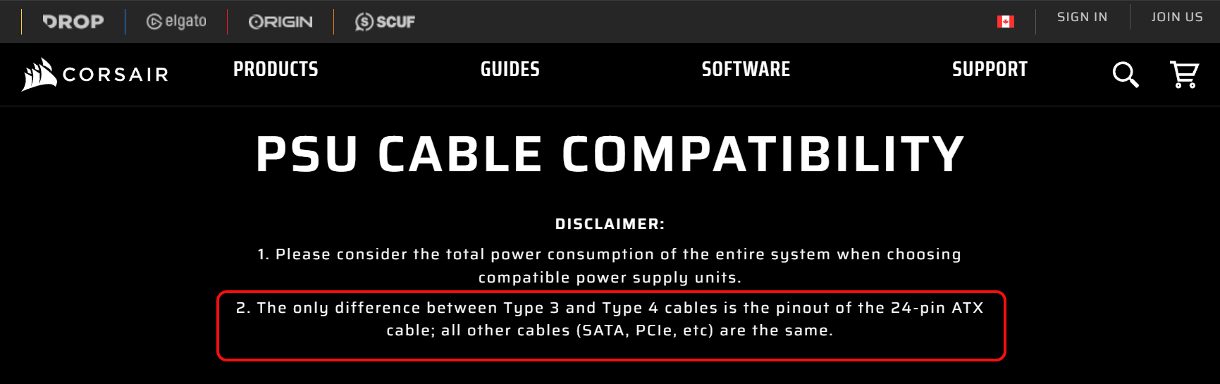
However, that is incorrect. Corsair’s blog states that the 24-pin cables have the same pin-outs, and that the PCIe and EPS12V cables are not the same. This is also incorrect, because the 24-pin cables have different pin-outs.
In summary, I understand all the above to mean that, except for the 24-pin ATX cable, type 4 cables are compatible with type 3 cables, but they provide cleaner power.
Diagnostics
Little diagnostic information is provided. "Use a paperclip," they say, and then they also mention that might not be very helpful. In general, paperclips have limited value as a diagnostic tool for debugging PSUs. Next, Corsair discusses how to use a PSU tester for an ATX 24-pin cable but does not talk about how to test the other cables.
Corsair provides a table on the same page showing pin signal levels for an ATX 2 24-pin cable but neglects to indicate how pins are numbered.
Pc-mods.com has color-coded pinout diagrams for Corsair® PSU Type 4 Cables.
Alternative Manufacturers
A brief search yielded the following PSU manufacturers, all of whom provide product support:
EVGA SuperNOVA 1000 GT
I purchased an EVGA SuperNOVA 1000 GT.
NewEgg now has a new AI-generated customer recommendation summary for their products, and those comments helped me make a purchasing decision. I recommend the NewEgg purchasing experience.

Setup
I opened the EVGA SuperNOVA 1000 GT box and found a proper printed manual, in color.
The manual showed a US phone number for support (888-881-3842) and an email address, support@evga.com.
The manual can be downloaded as a PDF. Pc-mods.com has color-coded pinout diagrams for all the cables supplied with this model PSU.
The included ‘tester’ is just a jumper that performs the same function as a paperclip. It is almost completely useless.
Knowing the proper cable for each motherboard or graphics card connector can be confusing. The following discusses how to work with the ATX 2.x and EPS connectors introduced above.
-
The PSU has an output labeled CPU1, and another labeled CPU2.
They are identical and interchangeable.
The cables labeled CPU are described in the manual as “EPS/ATX12V 8(4+4)-Pin x 1”,
which means that each EPS/ATX12V cable terminates with one motherboard connector.
These are meant to be plugged into your motherboard's CPU connectors, if present.
The EVGA SuperNOVA 1000 GT manual says on page 4:
However, the popular Intel Core i7-13700K processor has been measured with a peak power draw of 544 watts, and Core i9-13900K processors can draw at least as much for brief spikes.Connect the 4+4-Pin EPS12V cable to the motherboard. (Optional) – If you plan on extreme overclocking and your motherboard supports additional 8-Pin or 4-Pin CPU power connectors, connect the second 4+4-Pin EPS12V cable. This is only needed for heavy overclocking or for Dual CPU motherboards.
Note that these power spikes exceed the Max Turbo Power of 253 watts that Intel specifies for the Core i7-13700K and Core i9-13900K CPUs. This spike exceeds the rating for dual 4-pin CPU connectors discussed earlier. If you have a high-powered CPU, ignore the advice from EVGA and use both 4-pin CPU cables, because these CPUs might briefly require much of the 384 watts that two CPU cables are rated for. -
The PSU has 6 outputs labeled VGA1 through VGA5; there is no significance to the suffixes.
Each output is identical.
The cables labeled VGA are meant to be inserted into any convenient VGAx output,
and the other end is meant to plug into a PCIe device, such as a graphics card.
Two of the VGA cables have only one PCIe connector, while the other two VGA cables have two PCIe connectors. If your PCIe device has two power connectors, use both of the VGA cables with only one PCIe connector. This will provide more power to your PCIe device than using one VGA cable with two PCIe connectors.

The outermost VGA cable has a single PCIe connector, configured as a 6-pin plug.
The inner VGA cable has two PCIe connectors, configured as 8-pin plugs.
Magnification of the above image.

A Second New PSU DOA?
My tester showed the new EVGA PSU was out of spec. Two new PSUs from different manufacturers being dead on arrive seemed unlikely, so I attempted to contact EVGA PSU support.
Communication Breakdown
I called the EVGA tech support phone number on a Thursday at 4 PM ET (1 PM PT - California time), but the message said EVGA was closed until Monday at 9 AM PT. That was odd. I also called their other customer support phone number, (714) 528-4500, but got the same message.
I emailed EVGA’s support address, but the email bounced back with the following error.
<support@evga.com>: host d290004a.ess.barracudanetworks.com[209.222.82.255]
  said: 550 permanent failure for one or more recipients
  (support@evga.com:blocked) (in reply to end of DATA command)
I emailed their European support address, supportEU@evga, with the same error.
I then attempted enrolled in the EVGA Member online service. However, I could not log in due to several bizarre errors.
The following Monday I was able to call EVGA. I left a message.
A tech from EVGA called back the same day, then escalated to Chris Bencivenga, EVGA Operations Manager, who called the day after (Tuesday). Both of them were on top of things; they had read this article and done their homework.
I had a half-hour conversation with the second tech on July 16, 2024. Chris said that EVGA PSUs should pass using the type of tester that I used without beeping or flashing LEDs. Chris also said that their PG values are typically 70-85 ms. Chris offered to exchange my unit via prepaid AIR shipping and customs duty. I thought that was pretty nice.
It turned out that something about my email signature tripped EVGA’s spam filters. Once I sent plain text emails, my transmissions to EVGA succeeded.
Test the PSU Tester
I had one of the testers shown above for ten years. It worked well, until it did not. I believe my original PSU had died, then the old tester erroneously showed the Corsair replacement PSU and the EVGA PSU as being out of spec.
If a tester shows two or more new PSUs as being broken, doubt the tester. Even better, if your tester shows a PSU is failing, try testing with another tester to be sure. They are cheap enough to keep a spare.
A positive test can be trusted; however, a negative test (a failure) is inconclusive.
Success!
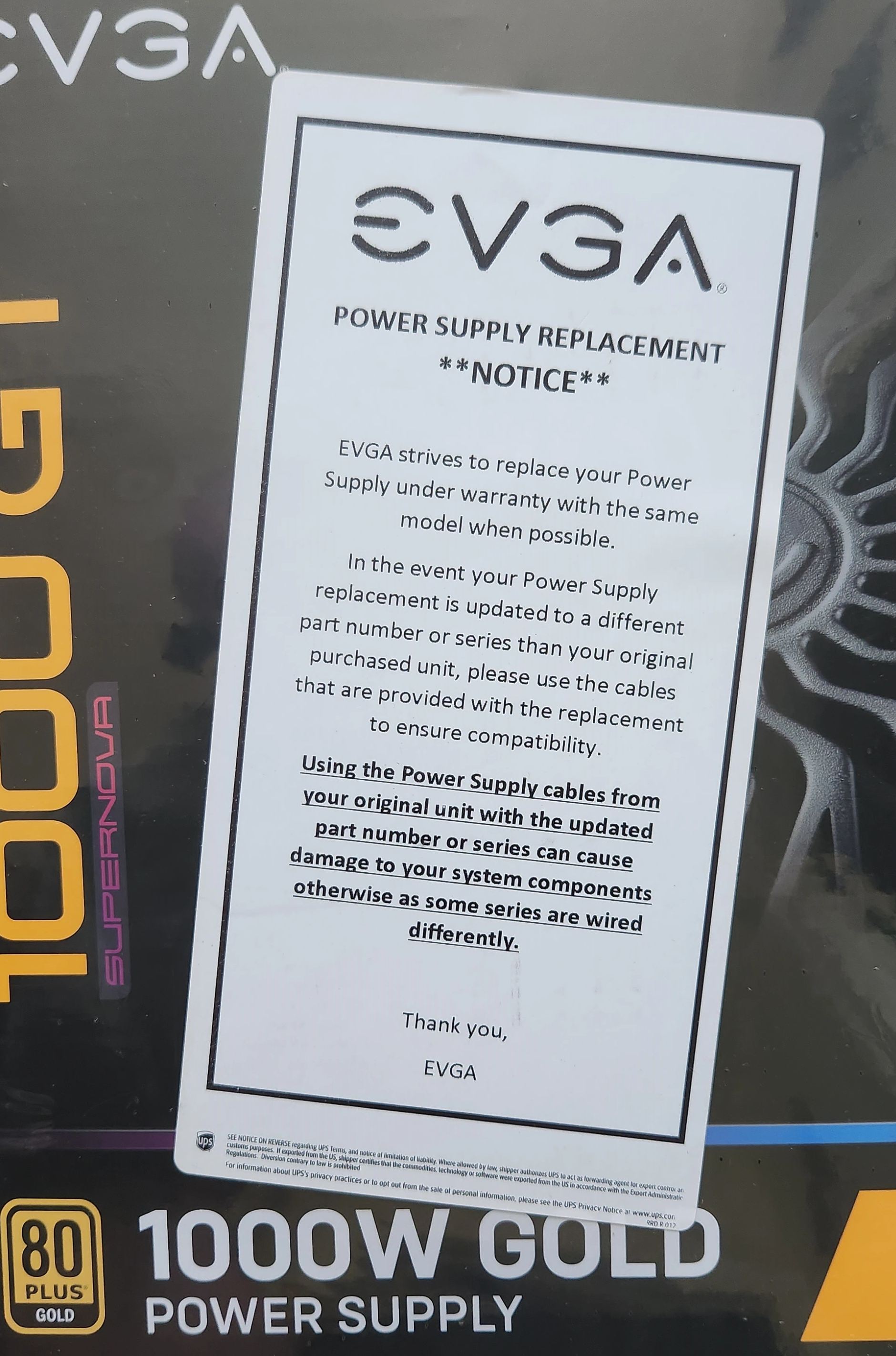
I received a replacement PSU from EVGA, and noticed a big warning about only using the cables that came with the PSU.
The EVGA SuperNOVA 1000 GT PSU passed with values of PG between 70 and 80 (ms).
Summary
- Replace all cables attached to a modular or semi-modular PSU when upgrading it.
- PSU testers are useful for your toolbox.
- A backup tester can provide greater confidence in the test results.
- Corsair’s policy of not providing technical support is ridiculous.
- EVGA provided excellent support.


