Published 1990-11-01.
Time to read: 9 minutes.
mentoring & advising collection.
Issues You’ll Face When Translating Between CAD Systems
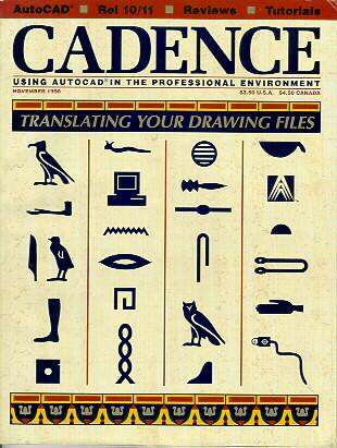
This was the lead article of the November 1990 issue of CADENCE Magazine.
It is said that language defines your view of the world. If you can’t describe something, you’ll probably have a hard time speaking about it or even thinking about it. The indigenous people of the Arctic, the Inuit, have more than 40 words which describe different kinds of snow – while we can talk about slush, powder snow, freezing rain, and a ‘big dump,’ English does not have the rich variety of vocabulary to describe snow simply because most English-speaking people’ s lives are not dominated by it.
Drawings are the language of technical people. In drafting class, students learn how to describe physical objects and their relationship with each other in a pictorial manner. Orthographic projection is a relatively recent presentation technique that has been popularized over the past 100 years. It allows people who are trained in the techniques of reading and writing orthogonal views to communicate 3D objects in a 2D medium. Considerable skill is required to represent complicated objects using orthographic projection.
Symbology is crucial to a drafter. This can take the form of an iconic marking, such as AutoCAD’s blocks and shapes, or with line styles to annotate hidden lines and centerlines. Cartographers make considerable use of symbology – just look at any map. You will see a unique line-type for rivers, another for major highways, another for secondary highways, another for dirt roads, and still another for township boundaries. To learn to drive around in strange cities and still arrive at our destination, we must learn to read maps and understand their symbology. If all the lines looked the same, we would not be able to distinguish a river from a road!
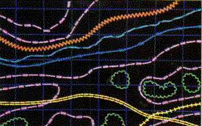
Line fonts (known in AutoCAD as line styles) are essential to annotate our drawings. Some mainframe CAD systems offer complex line fonts (Figure 1). These fonts are sometimes hard-coded into the software and are sometimes customizable. The operator draws the centerline and then applies the line font. Internally, the CAD system only stores the points entered, but the software represents them according to the line font associated with the line.
The various CAD systems available today have entities and symbology features that do not have a direct relationship between them. (An entity, also known as an object, is something you draw, like an arc, line or polyline). For example, the rat’s nest mesh in AutoCAD Release 11 is found on almost no other CAD system. (The rat’s nest mesh is rather unique in that each face in the mesh can be on a different layer, and the faces can be arbitrarily oriented.) To translate a rat’s nest back to AutoCAD Release 10, the user would have to explode it into faces. Although the drawing would look the same, the information relating the faces to each other would be lost. If you wanted to translate a rat’s nest into another CAD system that does not support faces, the best you could hope to accomplish would be a series of 3D lines around the outline of the mesh. Of course, hidden line removal would thus be impossible because the face information would be lost in the process.
A translator (or converter) is software that reads in drawing information in one format and produces a drawing in another format. The ‘source’ CAD system refers to the original CAD system. The ‘target’ or ‘destination’ CAD system refers to the desired resultant drawing format. For translation to be effective, the original drawings should contain entities common to both systems. That means that the drafter must use the “least common denominator” for both CAD systems.
Translator Myths
There is no perfect way to translate drawings when you need to choose between trade-offs. If you have a drawing made with “least common denominator” entities, the process should be relatively straightforward. In the general sense, however, complete translation is simply not possible; there is no way to teach CAD systems about the entities of other CAD systems.
In general, it is not possible to get a carbon copy translation of your drawing database from one CAD system into another. Yet you can successfully convert drawings if you know the common entities of the two CAD systems. Most CAD Systems have 2D and/or 3D lines, yet few have polylines with varying widths. Many do not support arcs in a polyline, just straight line arcs.
To correctly use translators, you need to distinguish between the appearance of a drawing
(its representation on paper or on the screen) and the drawing database (the entities stored in the database).
Drawings that may appear to be the same visually may not actually be good translations.
For example, in AutoCAD you can type SETVAR SKPOLY 1 to cause the Sketch command to generate polylines instead of lines.
If you then use the Sketch command to digitize in a long wiggly line like a river or road,
AutoCAD will make a single polyline with short, straight segments.
If you use a translator that explodes that polyline into numerous straight lines,
the result would be a drawing that looks the same but would not have the same information.
If you were to work on the converted drawing, you would realize that the many lines are not attached to each other.
The connectivity information embodied in the original polyline would have been lost even though the visual representation was preserved.
Conversely, entities that do not look the same may in fact be faithful translations of each other. Text fonts may not be identical between CAD systems, yet the textual information may be identical.
Of particular interest to cartographers and surveyors are custom line types (line types that continue across closely spaced vertices such as those found in splines and digitized lines). Many mainframe CAD systems such as Intergraph and Computervision support complex line types. If you are translating into AutoCAD from other CAD systems, there is software available to automatically annotate the drawings with the same line types that were used in the original drawings. Drawings annotated with the complex line types provided by mainframe CAD systems can be translated into AutoCAD and then reannotated. It does not actually create the special line fonts found in the mainframe CAD products but instead emits many individual entities that can be gathered up into unique blocks or placed on special layers. This is a clear example of how the raw data (points in a polyline) differs from the visual representation (custom linetype).
The National Bureau of Standards produced a standard for CAD system translators called IGES. It was intended to be a generalized neutral file format that could represent any type of CAD information and would allow all CAD systems to exchange drawings. The idea was that if CAD Systems could communicate by translating information into IGES format (which might retain all the original information, if IGES was perfect) then you could translate from IGES into the target CAD system format. As you have seen, this simply isn’t possible without losing information. Furthermore, IGES isn’t easy to work with, nor is it particularly useful. Harking back to our original analogy, imagine that you translated the Inuit’s description of the snow on the ski slopes into Esperanto, and then into English. You would undoubtedly learn less from the dual translation than you would from a direct Inuit to English translation.
The next time you go to a party with two or more bilingual people, try this game: seat each bilingual person in a circle such that they can converse in a language other than English with their immediate neighbors. For example, seat an English/French person next to a French/German person and a German/Italian person next to an Italian/English person. (For best results, invite people from non-European stock). Give each person a pad of paper and a pen. Start the game by writing a sentence on a piece or paper and pass it to the first person in the circle. Have them translate it in private and pass it in confidence to their neighbor. Once the sentence has made it around the circle, have each person read the message that they got. The results should be hilarious! Sentences with clichés or that are dependent on cultural context work best.
How Translation Works
The first issue you must solve when attempting to perform drawing translation is that of media compatibility. Mainframe and minicomputers often only support proprietary nine-track tape formats. You must convert the files stored on tape to files stored on your disk drive. This can be a difficult problem and should be solved by the party who produces the original CAD drawings. CAD drawings can be huge, so RS-232 or modem transfer is not a good solution. A simple and effective solution for connecting to an IBM mainframe would be to use an IRMA board in a PC.
Data storage format is also important. Most PCs use ASCII encoding to store character data, yet other formats exist. IBM’s mainframes, for example, use another encoding called EBCDIC. In addition, the order of bytes in the data might differ between source and destination CAD systems. Multi-byte data types such as real numbers can store the bytes in different order, and the number of bytes might differ. Internal representation usually varies between computers as well. However, the translator usually takes care of these issues automatically.
When choosing a translator, its input and output should be defined. If it can read the source CAD system’s binary drawing format but produces an AutoCAD script file, the translation will be very slow. If the output is a plot file, very little useful information will be retained in the conversion (the representation might be accurate, but the database would have been lost). If the output is DXF, you can deal with the next issue.
Most translators let you control the conversion process so that you can specify how entities are mapped (mapping describes the relationship between old entities, line styles and layers, and their representation in the target CAD system). You commonly do this by creating a cross-reference file that guides the translation process. Drawing standards must be rigidly adhered to in order for cross-reference files to be effective.
Using a cross-reference file, you map the layers, line styles, and entities in the original drawing to the target CAD system’s format. Information that you specify will control how the translator operates. For example, if the target CAD system does not have the same fonts as the original CAD system and you feel that the visual representation of text is more important than preserving the database, you might direct the translator to explode the original text into vectors. This would make editing the converted drawing an exercise in frustration, but it would look the same. Because of this, subcontractors who accept drawings from larger firms or government agencies, work on them, and then submit plots must sometimes go to great pains to explain to their client why they do not want to adhere to the client’s text font standards.
For best results, the translation should be performed on the original CAD system’s site and the converted drawing inspected there using the target CAD system. This would guarantee that the converted drawing has been created appropriately. Most suppliers of the original information do not have in-house knowledge of how to use the target CAD system, or even a computer system set up to run it, yet if the translation is to go smoothly they should bring in someone to verify that the information they send out is accurate and properly translated.
Purchasing Tips
Before purchasing a translator, have a sample drawing converted by the vendor (there may be a charge for this). Ask about any software maintenance problems that may be found with the software, as new versions of either CAD system may require updates to the translators. There may be a charge for updates or maintenance contracts.
Vendors of CAD translators should have support staff who are familiar with each of the CAD systems they support. Ask some probing questions; if you need to translate splines or polylines with embedded arcs, ask how they will come through the translation – will you get the entities you expect on the target CAD system? Make sure that you are satisfied with the vendor’s ability to answer questions and respond to problems before you purchase.
Ask for references who are in your line of work. Call them. Reference accounts are often reluctant to volunteer negative information, so you will need to ask the right questions. Was there anything that you had trouble with? Did you receive timely technical support? What has your experience been with updates?
The best way to find about translators is to ask your primary CAD vendor or refer to their source books. Look in the AutoCAD Third Party Source book or equivalent publications for other CAD vendors; you can also check the Third Party Software Guides of hardware vendors, if you have a Sun computer, you can check the CATALYST Source book.
When shopping for a translator, be very specific about the requirements. Describe the exact computing platforms that you need to translate between. For example, software running on Sun SPARCs will differ in their behavior between the North American and European versions. Also describe the versions of CAD software you need to translate between. Be specific about the media requirements. What you don’t know can hurt you. For example, Intergraph’s CAD database format varies depending on the computing platform on which it runs.
Michael Slinn is (was) president of M. Slinn Engineering, an AutoCAD third party developer with offices in Vancouver, British Columbia, Canada.
Acknowledgments
Thanks to Cliff Davis and Lindsay Baker of KRB, Inc. and Ralph Guditz of OCTAL, Inc. for their extensive information. Both companies specialize in producing translators.

